Control Flow Graph (CFG) Software Engineering
A Control Flow Graph (CFG) is the graphical representation of control flow or computation during the execution of programs or applications. Control flow graphs are mostly used in static analysis as well as compiler applications, as they can accurately represent the flow inside of a program unit. The control flow graph was originally developed by Frances E. Allen.
Control flow testing is a testing technique that comes under white box testing. The aim of this technique is to determine the execution order of statements or instructions of the program through a control structure. The control structure of a program is used to develop a test case for the program. In this technique, a particular part of a large program is selected by the tester to set the testing path. It is mostly used in unit testing. Test cases represented by the control graph of the program.
Control Flow Graph is formed from the node, edge, decision node, junction node to specify all possible execution path.
Notations used for Control Flow Graph
- Node
- Edge
- Decision Node
- Junction node
Node
Nodes in the control flow graph are used to create a path of procedures. Basically, it represents the sequence of procedures which procedure is next to come so, the tester can determine the sequence of occurrence of procedures.
We can see below in example the first node represent the start procedure and the next procedure is to assign the value of n after assigning the value there is decision node to decide next node of procedure as per the value of n if it is 18 or more than 18 so Eligible procedure will execute otherwise if it is less than 18 Not Eligible procedure executes. The next node is the junction node, and the last node is stop node to stop the procedure.
Edge
Edge in control flow graph is used to link the direction of nodes.
We can see below in example all arrows are used to link the nodes in an appropriate direction.
Decision node
Decision node in the control flow graph is used to decide next node of procedure as per the value.
We can see below in example decision node decide next node of procedure as per the value of n if it is 18 or more than 18 so Eligible procedure will execute otherwise if it is less than 18, Not Eligible procedure executes.
Junction node
Junction node in control flow graph is the point where at least three links meet.
Example
Diagram - control flow graph
The above example shows eligibility criteria of age for voting where if age is 18 or more than 18 so print message "You are eligible for voting" if it is less than 18 then print "You are not eligible for voting."
Program for this scenario is written above, and the control flow graph is designed for the testing purpose.
In the control flow graph, start, age, eligible, not eligible and stop are the nodes, n>=18 is a decision node to decide which part (if or else) will execute as per the given value. Connectivity of the eligible node and not eligible node is there on the stop node.
Test cases are designed through the flow graph of the programs to determine the execution path is correct or not. All nodes, junction, edges, and decision are the essential parts to design test cases.
Carhacteristics of Control Flow Graph:
- Control flow graph is process oriented.
- Control flow graph shows all the paths that can be traversed during a program execution.
- Control flow graph is a directed graph.
- Edges in CFG portray control flow paths and the nodes in CFG portray basic blocks.
There exist 2 designated blocks in Control Flow Graph:
- Entry Block:
Entry block allows the control to enter into the control flow graph. - Exit Block:
Control flow leaves through the exit block.
General Control Flow Graphs:
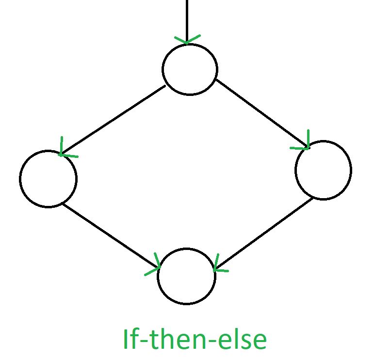
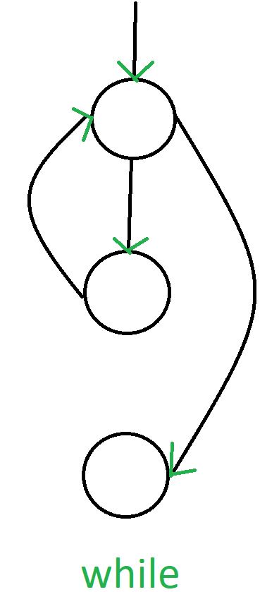
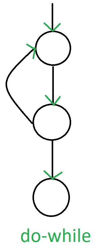
Control Flow Graph is represented differently for all statements and loops. Following images describe it:
1. If-else:

2. while:

3. do-while:

4. for:

Example:
if  A = 10 then
  if B > C
     A = B
  else A = C
  endif
  endif
print A, B, C
Flowchart of above example will be:

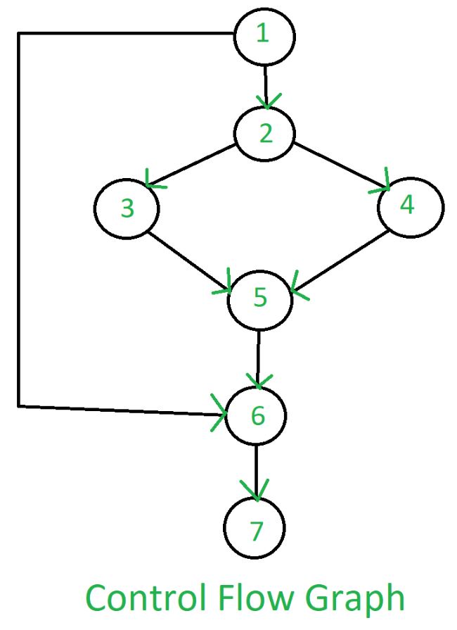
Control Flow Graph of above example will be:

Advantage of CFG:
There are many advantages of a control flow graph. It can easily encapsulate the information per each basic block. It can easily locate inaccessible codes of a program and syntactic structures such as loops are easy to find in a control flow graph.